|
Automatic calibration
|   |
|
Automatic calibration
| |
The automatic calibration is a standard feature of the measurement programs Plus and MT. The
aim is to correct the values with lenses, which have distortions or with lenses that view the
measurement object obliquely and thus allow a correct measurement to be made.
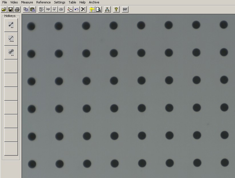
This requires a template with at least 6 (horizontal) x 5 (vertical) similar objects at
equal spacing from each other; your company must decide upon the required precision.
This example shows a point raster template with 2 mm spacing in X and Y.
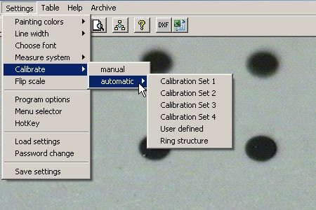
This menu item initiates the automatic calibration. If you use a template of your own then
go to the menu item "User-defined". If you use our templates, then select the number of
the template, which you use. The associated data are stored in the program.
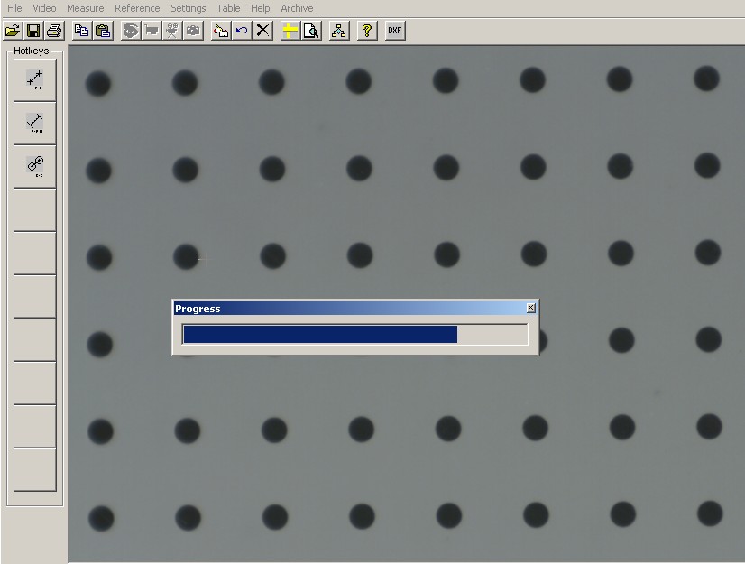
After the calibration has been initiated the progress bar shows you when the process is
complete.
After completing the process you will see a scale (provided no errors occurred), with
the following details :overall length; dimension of a scale line, and in brackets, the average
pixel size.If the arrow is shown instead of the hair cross, you can move the scale or the
related info strip by keeping the left mouse button pressed down.
Moving the scale will also move the info strip.
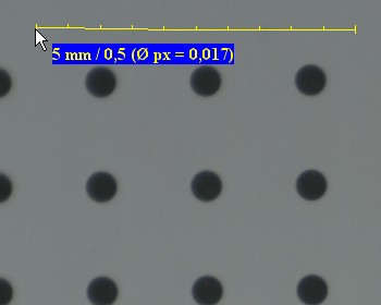
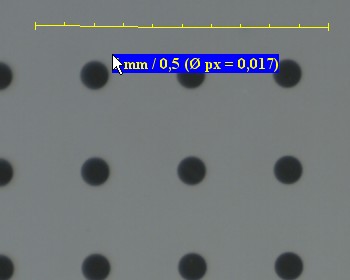
The "average" pixel size is shown because the dimensions in X and Y can be different.
You can find the precise values under "Modify Measuring System".
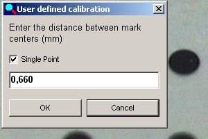
For a "User-defined template", when the calibration process is complete, the program
asks for the spacing between the objects. Enter the value here and then click on "OK".
Then proceed as above.
When the automatic calibration has been completed, all measurements and references
are adapted to the distortions.
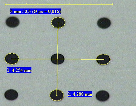
Example 1: circle to circle measurement oval circles.
Measured values are correct within the limits of pixel accuracy of 1 pixel.
Example 2: circles remain round.
Measured values show large deviations with manual calibration in one
direction (here the calibration was made in the X direction).
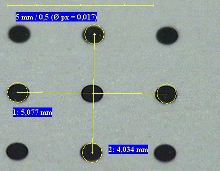
Here the X values agree but the Y values show a large difference between the left and
right images.
Example 2 shows a grid with a raster of 2 mm. Despite the distortion the intersection
points on the raster are drawn in the centre of the points.
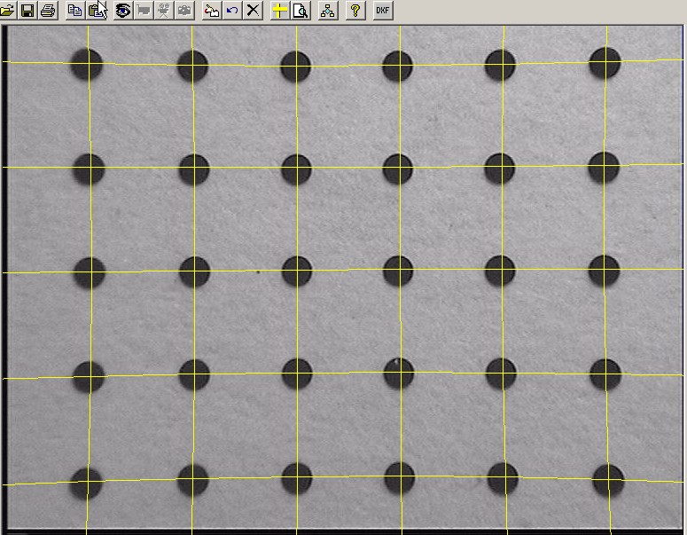
In the lower area in particular we see an asymmetric distortion from left to right, which
has been compensated for.
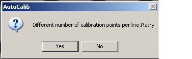
Possible errors in the automatic calibration: contamination
The template may be dirty. This results in more points being found in one direction than
the other. The error message is:
Check the template.
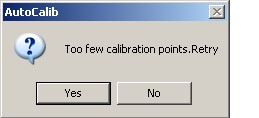
The template does not contain the correct number of calibration objects.
It may be necessary to line up the template again since some points lie on the edge.
The error message is:
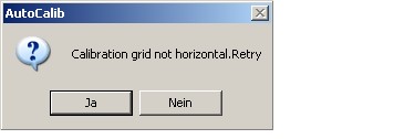
The template may only be under laid by a permitted skew of 10 pixels, since otherwise
the correction values would be too poor. The error message is:
Before repeating the process the template must be aligned again. You may want to
use the hair cross as an aid in making the alignment.
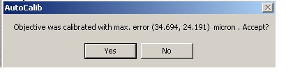
The template is so badly distorted that the correction calculation results in a value,
which is larger than 1 pixel. The message must be seen as more than a hint, since
the distortion is caused by the lens and can only be corrected by changing the lens.
You can also find the values obtained again under " Modify Measurement System".